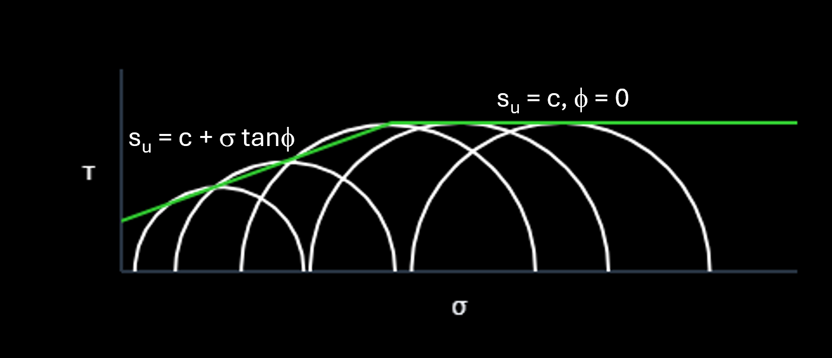
We know that the shear strength of soil is governed by effective stress. We also know that we can use total stress strength parameters to represent the undrained shear strength of clays. We use su = c and ϕ = 0 for saturated clays and su = c + σ tanϕ for partially saturated clays. Why do we do this, and why does it work?
If we load a clay very slowly, water will be able to move out of or into the clay's pores so that stress-induced pore water pressure does not build up. This would be a drained loading condition. If we know the pore water pressure condition (e.g., from the groundwater level or a seepage analysis), then we can evaluate the effective stress and use s = c' + σ' tanϕ'.
This isn't the case in standard construction because clays have low permeability values. The loading condition is usually undrained, not drained. In undrained loading, the clay develops stress-induced pore water pressure as the load is applied. And here's the thing: we hardly ever know the magnitude of the stress-induced pore water pressure in the field. If we don't know the pore water pressure, then we don't know the effective stress and we can't use s = c' + σ' tanϕ'.
Let's focus on saturated clays. We use su = c and ϕ = 0 to represent their undrained shear strength. To understand why this works, let's simulate a clay's behavior when loaded undrained.
We'll use pore pressure parameters to evaluate the stress-induced pore water pressure. Skempton introduced the concept of pore pressure parameters in 1954.
The first step is to divide the change in total stress acting on the clay (i.e., the load) into two parts: Δσ3 and Δσd. In the figure below, the initial stress condition is isotropic: σ3i = σ1i. The Mohr circle here is a Mohr dot with zero diameter. The final stress condition is represented by the Mohr circle with σ3f and σ1f. The value of Δσ3 is straightforward: σ3f − σ3i. This is a change in the all-around total stress acting on the clay. The diameter of a Mohr circle is called the deviator stress: σd = σ1 − σ3. The value of Δσd is then the change in the diameter of the Mohr circle, which reflects the change in shear stress acting on the clay. For the case shown in the figure, Δσd = σ1f − σ3f.
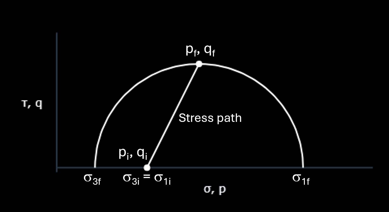
We can represent the change in total stress conditions by using a stress path. A stress path just tracks the top of the Mohr circle as it changes. The coordinates of each point on a stress path are p and q, where p = (σ1 + σ3)/2 and q = (σ1 − σ3)/2. The coordinate p is the average normal stress and the coordinate q is the maximum shear stress.
We'll use simple, straight-line stress paths on this website. The slope of a stress path will be T = Δp/Δq. This isn't the rise over the run. It's the run over the rise. Think of it as how p changes as q increases during loading: Δp = TΔq.
Now back to the pore pressure parameters. Each part of the overall change in total stress causes a corresponding change in pore water pressure:
Δua = BΔσ3
Δud = A̅Δσd
For saturated clays, B = 1. When the all-around total stress changes, the pore water pressure changes by the same amount. The value of A̅ depends on the specific clay, the OCR, the initial consolidation condition (isotropic or anisotropic), and the shear stress level. It can range from 1.5 for highly sensitive clays to −0.5 for heavily overconsolidated clays. The value of A̅ tells us how the pore water pressure changes in response to changes in shear stress (as represented by Δσd).
(Think of what's happening inside an element of saturated clay. When an all-around stress is applied, the pore water, which is less compressible than the soil structure, takes all the load. This is why B = 1. When a shear stress is applied, the clay may have a tendency to contract (if it's soft) or dilate (if it's stiff). A saturated clay doesn't change volume during undrained loading. Instead, a clay that "wants" to contract will generate positive shearing-induced pore water pressure. And a clay that "wants" to dilate will generate negative shearing-induced pore water pressure.)
It will be more illustrative to express the components of the stress-induced pore water pressure in terms of Δp and Δq as opposed to Δσ3 and Δσd. Can you see from the figure above that σ3 = p − q, σ1 = p + q, and σd = 2q?
Now we can express Δua as the sum of two parts: Δuap + Δuaq, where Δuap = TΔq and Δuaq = −Δq. Here is how we got this:
Δσ3 = Δp − Δq
Δua = Δσ3 (for B = 1)
Δua = Δp − Δq
Δua = Δuap + Δuaq
with Δuap = Δp = TΔq and Δuaq = −Δq
And we can express Δud as 2A̅Δq.
We'll use the cornerstone relationship of soil mechanics, σ' = σ − u, to evaluate how the effective stress changes during the undrained loading simulation. The coordinates of the top of the effective stress Mohr circle are p' and q, where p' = (σ'1 + σ'3)/2 and q = (σ'1 − σ'3)/2. Note that q for the effective stress circle is the same as q for the total stress circle.
Before the loading begins, we can use the initial total stress (pi) and the initial pore water pressure (ui) to evaluate the initial effective stress: p'i = pi − ui.
When tracking how the effective stress changes during the loading, we'll be tracking how p' changes:
Δp' = Δp − Δu
Δp' = Δp − (Δui + Δuap + Δuaq + Δud)
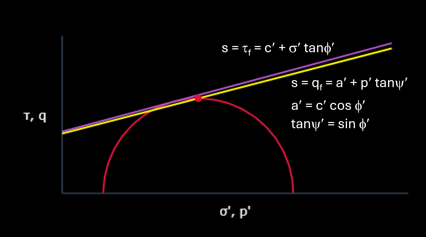
Since we're evaluating the effective stress in our undrained loading simulation, we can use s = c' + σ' tanϕ' to evaluate the shear strength. The figure below shows an effective stress Mohr circle at failure. The circle is just touching the Mohr-Coulomb failure line (purple). We can express the same failure condition using a failure line (yellow) that goes through the top of the Mohr circle. The equation for this line is shown in the figure. The clay in our simulation will fail when its stress path hits this line.
Let's run the simulation already! In the boxes below, you can enter values of pi and T for three cases. The pi for case 1 must be the lowest of the three. The value of p'i will be computed as the pi for case 1 minus ui. All three cases will have the same value of p'i (this is important for what we're trying to learn). The value of ui for cases 2 and 3 will be adjusted to make this work. Finally, enter a value for A̅.
The clay in the simulation has the following effective stress shear strength parameters: c' = 75 and ϕ' = 15. We're not going to worry here about the reasonableness of the various combinations of p'i, A̅, c', and ϕ' that will arise. We're not even considering the clay's preconsolidation pressure and OCR. What matters here is that there is an effective stress failure line for the clay.
The table and figures below show the results of the simulation.